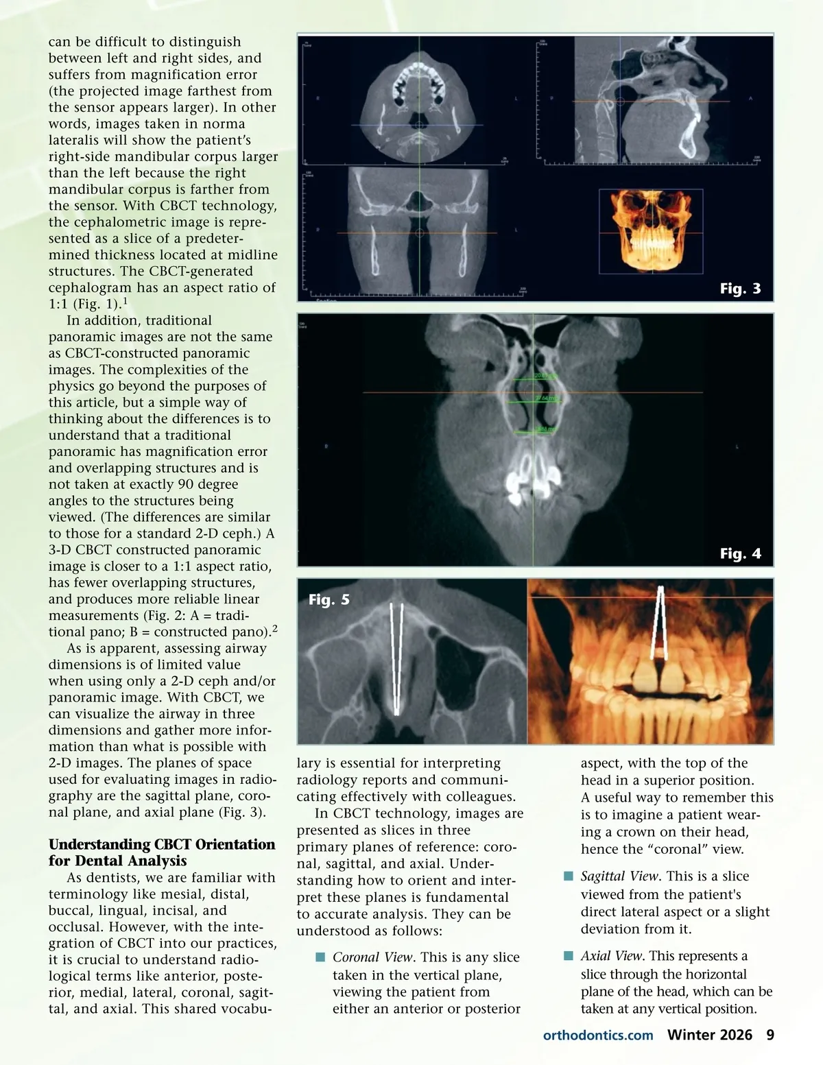
can be difficult to distinguish between left and right sides, and suffers from magnification error (the projected image farthest from the sensor appears larger). In other words, images taken in norma lateralis will show the patient’s right-side mandibular corpus larger than the left because the right mandibular corpus is farther from the sensor. With CBCT technology, the cephalometric image is repre-sented as a slice of a predeter-mined thickness located at midline structures. The CBCT-generated cephalogram has an aspect ratio of 1:1 (Fig. 1). 1 In addition, traditional panoramic images are not the same as CBCT-constructed panoramic images. The complexities of the physics go beyond the purposes of this article, but a simple way of thinking about the differences is to understand that a traditional panoramic has magnification error and overlapping structures and is not taken at exactly 90 degree angles to the structures being viewed. (The differences are similar to those for a standard 2-D ceph.) A 3-D CBCT constructed panoramic image is closer to a 1:1 aspect ratio, has fewer overlapping structures, and produces more reliable linear measurements (Fig. 2: A = tradi-tional pano; B = constructed pano). 2 As is apparent, assessing airway dimensions is of limited value when using only a 2-D ceph and/or panoramic image. With CBCT, we can visualize the airway in three dimensions and gather more infor-mation than what is possible with 2-D images. The planes of space used for evaluating images in radio-graphy are the sagittal plane, coro-nal plane, and axial plane (Fig. 3). Fig. 3 Fig. 4 Fig. 5 Understanding CBCT Orientation for Dental Analysis As dentists, we are familiar with terminology like mesial, distal, buccal, lingual, incisal, and occlusal. However, with the inte-gration of CBCT into our practices, it is crucial to understand radio-logical terms like anterior, poste-rior, medial, lateral, coronal, sagit-tal, and axial. This shared vocabu-lary is essential for interpreting radiology reports and communi-cating effectively with colleagues. In CBCT technology, images are presented as slices in three primary planes of reference: coro-nal, sagittal, and axial. Under-standing how to orient and inter-pret these planes is fundamental to accurate analysis. They can be understood as follows: í Coronal View . This is any slice taken in the vertical plane, viewing the patient from either an anterior or posterior aspect, with the top of the head in a superior position. A useful way to remember this is to imagine a patient wear-ing a crown on their head, hence the “coronal” view. í Sagittal View . This is a slice viewed from the patient's direct lateral aspect or a slight deviation from it. í Axial View . This represents a slice through the horizontal plane of the head, which can be taken at any vertical position. orthodontics.com Winter 2026 9
Journal of the American Orthodontic Society Winter 2026: Page 9