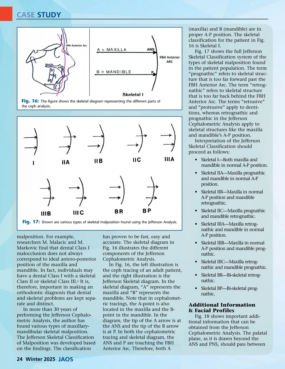
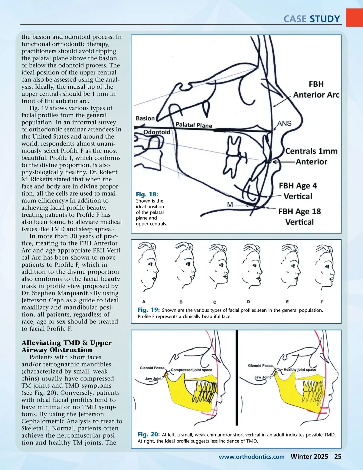
CASE STUDY (maxilla) and B (mandible) are in proper A-P position. The skeletal classification for the patient in Fig. 16 is Skeletal I. Fig. 17 shows the full Jefferson Skeletal Classification system of the types of skeletal malposition found in the patient population. The term “prognathic” refers to skeletal struc-ture that is too far forward past the FBH Anterior Arc. The term “retrog-nathic” refers to skeletal structure that is too far back behind the FBH Anterior Arc. The terms “retrusive” and “protrusive” apply to denti-tions, whereas retrognathic and prognathic in the Jefferson Cephalometric Analysis apply to skeletal structures like the maxilla and mandible’s A-P position. Interpretation of the Jefferson Skeletal Classification should proceed as follows: • Skeletal I—Both maxilla and mandible in normal A-P position. • Skeletal IIA—Maxilla prognathic and mandible in normal A-P position. • Skeletal IIB—Maxilla in normal A-P position and mandible retrognathic. • Skeletal IIC—Maxilla prognathic and mandible retrognathic. Fig. 17: Shown are various types of skeletal malposition found using the Jefferson Analysis. malposition. For example, researchers M. Malacic and M. Markovic find that dental Class I malocclusion does not always correspond to ideal antero-posterior position of the maxilla and mandible. In fact, individuals may have a dental Class I with a skeletal Class II or skeletal Class III. 5 It is, therefore, important in making an orthodontic diagnosis that dental and skeletal problems are kept sepa-rate and distinct. In more than 30 years of performing the Jefferson Cephalo-metric Analysis, the author has found various types of maxillary-mandibular skeletal malposition. The Jefferson Skeletal Classification of Malposition was developed based on the findings. The classification has proven to be fast, easy and accurate. The skeletal diagram in Fig. 16 illustrates the different components of the Jefferson Cephalometric Analysis. In Fig. 16, the left illustration is the ceph tracing of an adult patient, and the right illustration is the Jefferson Skeletal diagram. In the skeletal diagram, “A” represents the maxilla and “B” represents the mandible. Note that in cephalomet-ric tracings, the A-point is also located in the maxilla and the B-point in the mandible. In the diagram, the tip of the A arrow is at the ANS and the tip of the B arrow is at P. In both the cephalometric tracing and skeletal diagram, the ANS and P are touching the FBH Anterior Arc. Therefore, both A • Skeletal IIIA—Maxilla retrog-nathic and mandible in normal A-P position. • Skeletal IIIB—Maxilla in normal A-P position and mandible prog-nathic. • Skeletal IIIC—Maxilla retrog-nathic and mandible prognathic. • Skeletal BR—Bi-skeletal retrog-nathic. • Skeletal BP—Bi-skeletal prog-nathic. Fig. 16: The figure shows the skeletal diagram representing the different parts of the ceph analysis. Additional Information & Facial Profiles Fig. 18 shows important addi-tional information that can be obtained from the Jefferson Cephalometric Analysis. The palatal plane, as it is drawn beyond the ANS and PNS, should pass between 24 Winter 2025 JAOS
Journal of the American Orthodontic Society Winter 2025: Page 24