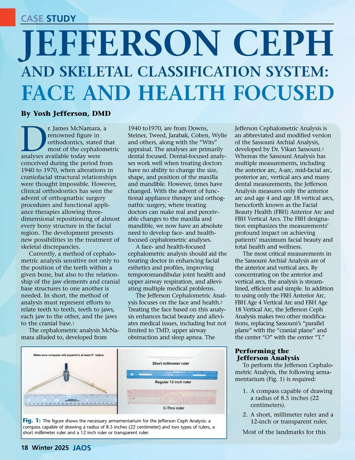
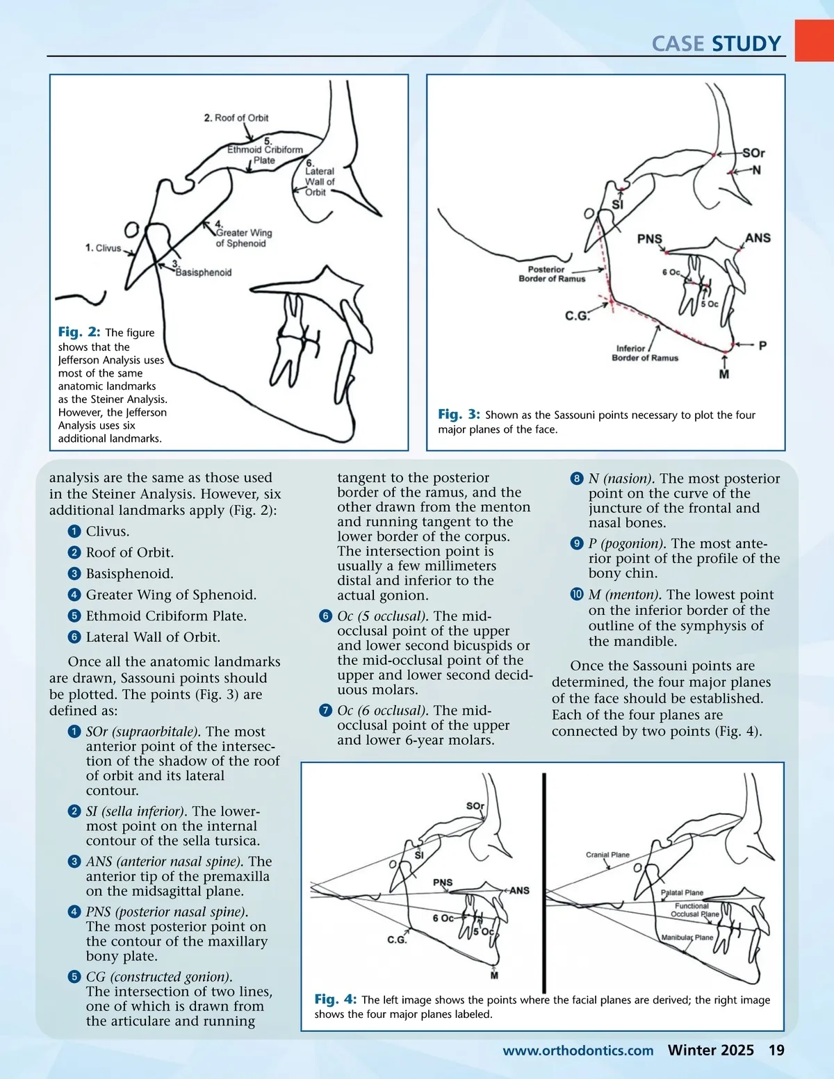
CASE STUDY Fig. 2: The figure shows that the Jefferson Analysis uses most of the same anatomic landmarks as the Steiner Analysis. However, the Jefferson Analysis uses six additional landmarks. Fig. 3: Shown as the Sassouni points necessary to plot the four major planes of the face. analysis are the same as those used in the Steiner Analysis. However, six additional landmarks apply (Fig. 2): ᕡ Clivus. ᕢ Roof of Orbit. ᕣ Basisphenoid. ᕤ Greater Wing of Sphenoid. ᕥ Ethmoid Cribiform Plate. ᕦ Lateral Wall of Orbit. Once all the anatomic landmarks are drawn, Sassouni points should be plotted. The points (Fig. 3) are defined as: ᕡ SOr (supraorbitale). The most anterior point of the intersec-tion of the shadow of the roof of orbit and its lateral contour. ᕢ SI (sella inferior) . The lower-most point on the internal contour of the sella tursica. ᕣ ANS (anterior nasal spine). The anterior tip of the premaxilla on the midsagittal plane. ᕤ PNS (posterior nasal spine). The most posterior point on the contour of the maxillary bony plate. ᕥ CG (constructed gonion). The intersection of two lines, one of which is drawn from the articulare and running tangent to the posterior border of the ramus, and the other drawn from the menton and running tangent to the lower border of the corpus. The intersection point is usually a few millimeters distal and inferior to the actual gonion. ᕦ Oc (5 occlusal). The mid-occlusal point of the upper and lower second bicuspids or the mid-occlusal point of the upper and lower second decid-uous molars. ᕧ Oc (6 occlusal). The mid-occlusal point of the upper and lower 6-year molars. ᕨ N (nasion). The most posterior point on the curve of the juncture of the frontal and nasal bones. ᕩ P (pogonion). The most ante-rior point of the profile of the bony chin. µ M (menton). The lowest point on the inferior border of the outline of the symphysis of the mandible. Once the Sassouni points are determined, the four major planes of the face should be established. Each of the four planes are connected by two points (Fig. 4). Fig. 4: The left image shows the points where the facial planes are derived; the right image shows the four major planes labeled. www.orthodontics.com Winter 2025 19
Journal of the American Orthodontic Society Winter 2025: Page 19