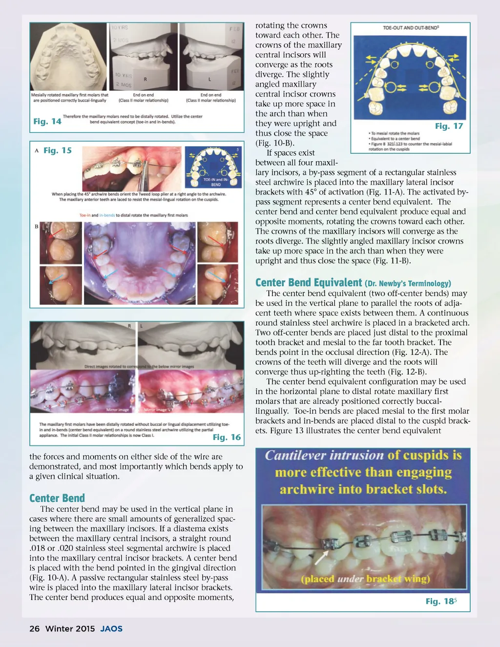
Fig. 14 Fig. 15 rotating the crowns toward each other. The crowns of the maxillary central incisors will converge as the roots diverge. The slightly angled maxillary central incisor crowns take up more space in the arch than when they were upright and Fig. 17 thus close the space (Fig. 10-B). If spaces exist between all four maxil-lary incisors, a by-pass segment of a rectangular stainless steel archwire is placed into the maxillary lateral incisor brackets with 45° of activation (Fig. 11-A). The activated by-pass segment represents a center bend equivalent. The center bend and center bend equivalent produce equal and opposite moments, rotating the crowns toward each other. The crowns of the maxillary incisors will converge as the roots diverge. The slightly angled maxillary incisor crowns take up more space in the arch than when they were upright and thus close the space (Fig. 11-B). Center Bend Equivalent (Dr. Newby’s Terminology) The center bend equivalent (two off-center bends) may be used in the vertical plane to parallel the roots of adja-cent teeth where space exists between them. A continuous round stainless steel archwire is placed in a bracketed arch. Two off-center bends are placed just distal to the proximal tooth bracket and mesial to the far tooth bracket. The bends point in the occlusal direction (Fig. 12-A). The crowns of the teeth will diverge and the roots will converge thus up-righting the teeth (Fig. 12-B). The center bend equivalent configuration may be used in the horizontal plane to distal rotate maxillary first molars that are already positioned correctly buccal-lingually. Toe-in bends are placed mesial to the first molar brackets and in-bends are placed distal to the cuspid brack-ets. Figure 13 illustrates the center bend equivalent Fig. 16 the forces and moments on either side of the wire are demonstrated, and most importantly which bends apply to a given clinical situation. Center Bend The center bend may be used in the vertical plane in cases where there are small amounts of generalized spac-ing between the maxillary incisors. If a diastema exists between the maxillary central incisors, a straight round .018 or .020 stainless steel segmental archwire is placed into the maxillary central incisor brackets. A center bend is placed with the bend pointed in the gingival direction (Fig. 10-A). A passive rectangular stainless steel by-pass wire is placed into the maxillary lateral incisor brackets. The center bend produces equal and opposite moments, Fig. 18 5 26 Winter 2015 JAOS
Journal of the American Orthodontic Society Winter 2015: Page 26