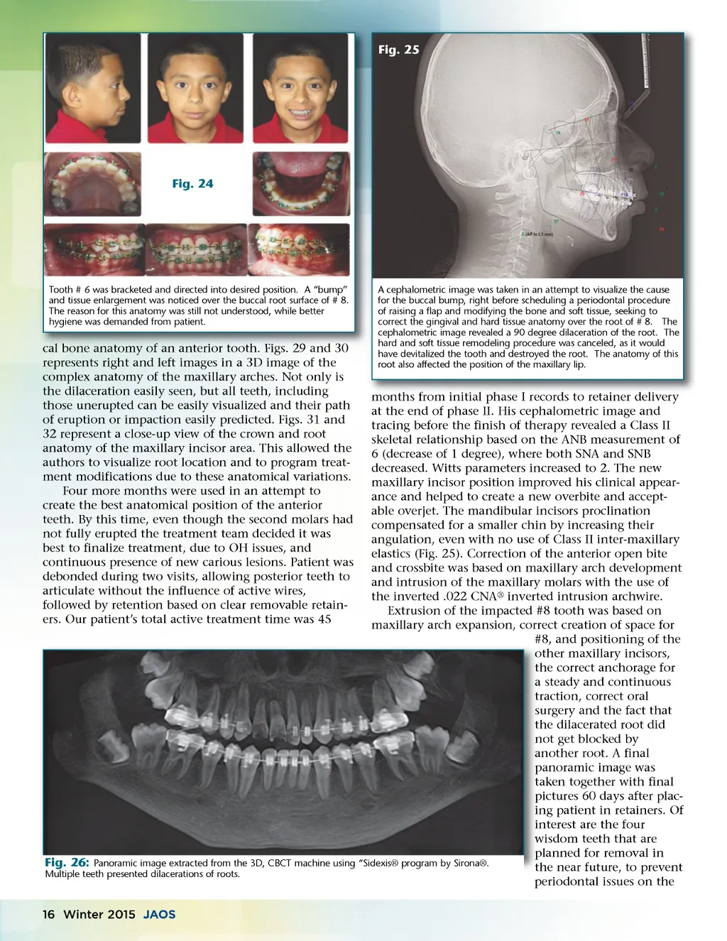
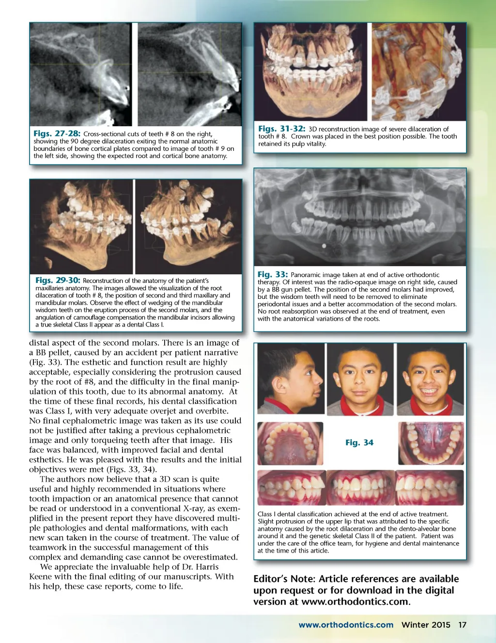
Fig. 25 Fig. 24 Tooth # 6 was bracketed and directed into desired position. A “bump” and tissue enlargement was noticed over the buccal root surface of # 8. The reason for this anatomy was still not understood, while better hygiene was demanded from patient. tooth. Figs Figs. 29 and 30 cal bone anatomy of an anterior tooth represents right and left images in a 3D image of the complex anatomy of the maxillary arches. Not only is the dilaceration easily seen, but all teeth, including those unerupted can be easily visualized and their path of eruption or impaction easily predicted. Figs. 31 and 32 represent a close-up view of the crown and root anatomy of the maxillary incisor area. This allowed the authors to visualize root location and to program treat-ment modifications due to these anatomical variations. Four more months were used in an attempt to create the best anatomical position of the anterior teeth. By this time, even though the second molars had not fully erupted the treatment team decided it was best to finalize treatment, due to OH issues, and continuous presence of new carious lesions. Patient was debonded during two visits, allowing posterior teeth to articulate without the influence of active wires, followed by retention based on clear removable retain-ers. Our patient’s total active treatment time was 45 A cephalometric image was taken in an attempt to visualize the cause for the buccal bump, right before scheduling a periodontal procedure of raising a flap and modifying the bone and soft tissue, seeking to correct the gingival and hard tissue anatomy over the root of # 8. The cephalometric image revealed a 90 degree dilaceration of the root. The hard and soft tissue remodeling procedure was canceled, as it would have devitalized the tooth and destroyed the root. The anatomy of this root also affected the position of the maxillary lip. months from initial phase I records to retainer delivery at the end of phase II. His cephalometric image and tracing before the finish of therapy revealed a Class II skeletal relationship based on the ANB measurement of 6 (decrease of 1 degree), where both SNA and SNB decreased. Witts parameters increased to 2. The new maxillary incisor position improved his clinical appear-ance and helped to create a new overbite and accept-able overjet. The mandibular incisors proclination compensated for a smaller chin by increasing their angulation, even with no use of Class II inter-maxillary elastics (Fig. 25). Correction of the anterior open bite and crossbite was based on maxillary arch development and intrusion of the maxillary molars with the use of the inverted .022 CNA ® inverted intrusion archwire. Extrusion of the impacted #8 tooth was based on maxillary arch expansion, correct creation of space for #8, and positioning of the o other maxillary incisors, t the correct anchorage for a steady and continuous t traction, correct oral s surgery and the fact that t the dilacerated root did n not get blocked by a another root. A final p panoramic image was t taken together with final pictures 60 days after plac-p ing patient in retainers. Of in interest are the four in wisdom teeth that are w planned for removal in p Fig. 26: Panoramic image extracted from the 3D, CBCT machine using “Sidexis® program by Sirona®. the near future, to prevent t Multiple teeth presented dilacerations of roots. periodontal issues on the 16 Winter 2015 JAOS
Journal of the American Orthodontic Society Winter 2015: Page 16