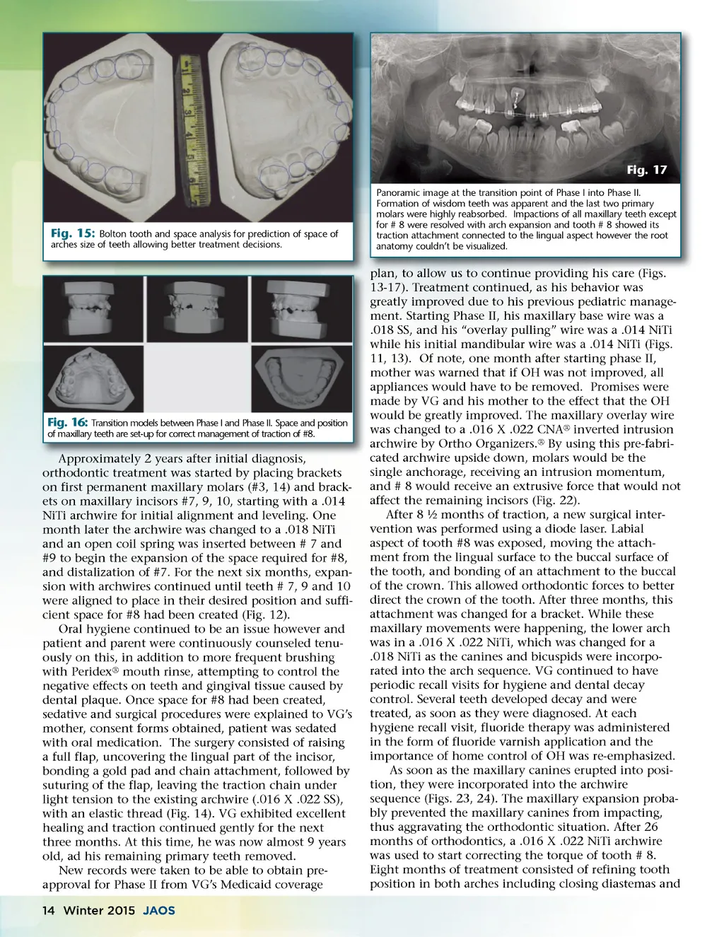
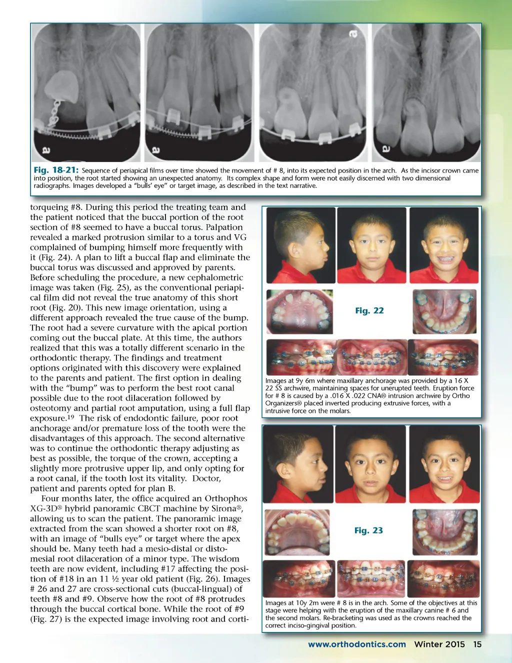
Fig. 18-21: Sequence of periapical films over time showed the movement of # 8, into its expected position in the arch. As the incisor crown came into position, the root started showing an unexpected anatomy. Its complex shape and form were not easily discerned with two dimensional radiographs. Images developed a “bulls’ eye” or target image, as described in the text narrative. #8. During this period the treating team and torqueing #8 the patient noticed that the buccal portion of the root section of #8 seemed to have a buccal torus. Palpation revealed a marked protrusion similar to a torus and VG complained of bumping himself more frequently with it (Fig. 24). A plan to lift a buccal flap and eliminate the buccal torus was discussed and approved by parents. Before scheduling the procedure, a new cephalometric image was taken (Fig. 25), as the conventional periapi-cal film did not reveal the true anatomy of this short root (Fig. 20). This new image orientation, using a different approach revealed the true cause of the bump. The root had a severe curvature with the apical portion coming out the buccal plate. At this time, the authors realized that this was a totally different scenario in the orthodontic therapy. The findings and treatment options originated with this discovery were explained to the parents and patient. The first option in dealing with the “bump” was to perform the best root canal possible due to the root dilaceration followed by osteotomy and partial root amputation, using a full flap exposure. 19 The risk of endodontic failure, poor root anchorage and/or premature loss of the tooth were the disadvantages of this approach. The second alternative was to continue the orthodontic therapy adjusting as best as possible, the torque of the crown, accepting a slightly more protrusive upper lip, and only opting for a root canal, if the tooth lost its vitality. Doctor, patient and parents opted for plan B. Four months later, the office acquired an Orthophos XG-3D ® hybrid panoramic CBCT machine by Sirona ® , allowing us to scan the patient. The panoramic image extracted from the scan showed a shorter root on #8, with an image of “bulls eye” or target where the apex should be. Many teeth had a mesio-distal or disto-mesial root dilaceration of a minor type. The wisdom teeth are now evident, including #17 affecting the posi-tion of #18 in an 11 ½ year old patient (Fig. 26). Images # 26 and 27 are cross-sectional cuts (buccal-lingual) of teeth #8 and #9. Observe how the root of #8 protrudes through the buccal cortical bone. While the root of #9 (Fig. 27) is the expected image involving root and corti-Fig. 22 Images at 9y 6m where maxillary anchorage was provided by a 16 X 22 SS archwire, maintaining spaces for unerupted teeth. Eruption force for # 8 is caused by a .016 X .022 CNA® intrusion archwire by Ortho Organizers® placed inverted producing extrusive forces, with a intrusive force on the molars. Fig. 23 Images at 10y 2m were # 8 is in the arch. Some of the objectives at this stage were helping with the eruption of the maxillary canine # 6 and the second molars. Re-bracketing was used as the crowns reached the correct inciso-gingival position. www.orthodontics.com www orthodontics com Winter 2015 15
Journal of the American Orthodontic Society Winter 2015: Page 15