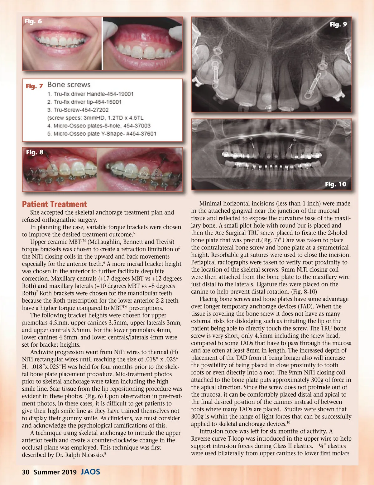
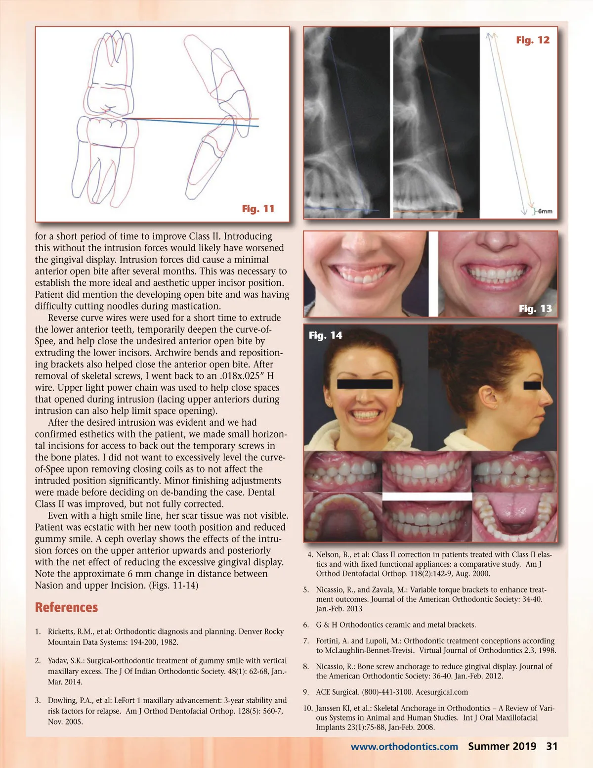
Fig. 6 Fig. 9 Fig. 7 Fig. 8 Fig. 10 Patient Treatment She accepted the skeletal anchorage treatment plan and refused orthognathic surgery. In planning the case, variable torque brackets were chosen to improve the desired treatment outcome. 5 Upper ceramic MBT TM (McLaughlin, Bennett and Trevisi) torque brackets was chosen to create a retraction limitation of the NiTi closing coils in the upward and back movements especially for the anterior teeth. 6 A more incisal bracket height was chosen in the anterior to further facilitate deep bite correction. Maxillary centrals (+17 degrees MBT vs +12 degrees Roth) and maxillary laterals (+10 degrees MBT vs +8 degrees Roth) 7 Roth brackets were chosen for the mandibular teeth because the Roth prescription for the lower anterior 2-2 teeth have a higher torque compared to MBT TM prescriptions. The following bracket heights were chosen for upper premolars 4.5mm, upper canines 3.5mm, upper laterals 3mm, and upper centrals 3.5mm. For the lower premolars 4mm, lower canines 4.5mm, and lower centrals/laterals 4mm were set for bracket heights. Archwire progression went from NiTi wires to thermal (H) NiTi rectangular wires until reaching the size of .018” x .025” H. .018”x.025”H was held for four months prior to the skele-tal bone plate placement procedure. Mid-treatment photos prior to skeletal anchorage were taken including the high smile line. Scar tissue from the lip repositioning procedure was evident in these photos. (Fig. 6) Upon observation in pre-treat-ment photos, in these cases, it is difficult to get patients to give their high smile line as they have trained themselves not to display their gummy smile. As clinicians, we must consider and acknowledge the psychological ramifications of this. A technique using skeletal anchorage to intrude the upper anterior teeth and create a counter-clockwise change in the occlusal plane was employed. This technique was first described by Dr. Ralph Nicassio. 8 Minimal horizontal incisions (less than 1 inch) were made in the attached gingival near the junction of the mucosal tissue and reflected to expose the curvature base of the maxil-lary bone. A small pilot hole with round bur is placed and then the Ace Surgical TRU screw placed to fixate the 2-holed bone plate that was precut.(Fig. 7) 9 Care was taken to place the contralateral bone screw and bone plate at a symmetrical height. Resorbable gut sutures were used to close the incision. Periapical radiographs were taken to verify root proximity to the location of the skeletal screws. 9mm NiTi closing coil were then attached from the bone plate to the maxillary wire just distal to the laterals. Ligature ties were placed on the canine to help prevent distal rotation. (Fig. 8-10) Placing bone screws and bone plates have some advantage over longer temporary anchorage devices (TAD). When the tissue is covering the bone screw it does not have as many external risks for dislodging such as irritating the lip or the patient being able to directly touch the screw. The TRU bone screw is very short, only 4.5mm including the screw head, compared to some TADs that have to pass through the mucosa and are often at least 8mm in length. The increased depth of placement of the TAD from it being longer also will increase the possibility of being placed in close proximity to tooth roots or even directly into a root. The 9mm NiTi closing coil attached to the bone plate puts approximately 300g of force in the apical direction. Since the screw does not protrude out of the mucosa, it can be comfortably placed distal and apical to the final desired position of the canines instead of between roots where many TADs are placed. Studies were shown that 300g is within the range of light forces that can be successfully applied to skeletal anchorage devices. 10 Intrusion force was left for six months of activity. A Reverse curve T-loop was introduced in the upper wire to help support intrusion forces during Class II elastics. ¼” elastics were used bilaterally from upper canines to lower first molars 30 Summer 2019 JAOS
Journal of the American Orthodontic Society Summer 2019: Page 30