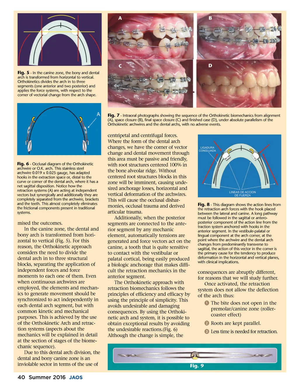
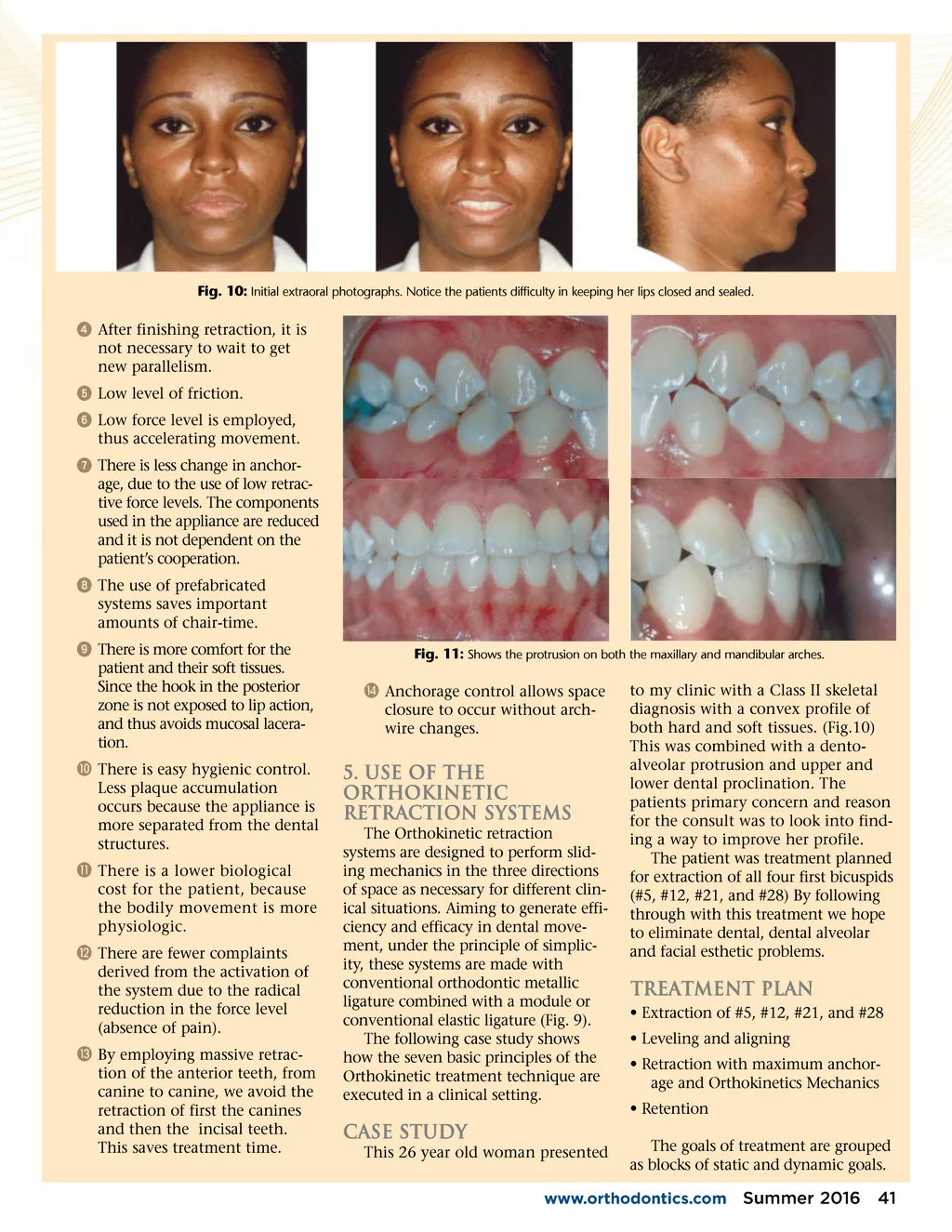
A B C Fig. 5 -In the canine zone, the bony and dental arch is transformed from horizontal to vertical. Orthokinetics divides the arch in to three segments (one anterior and two posterior) and applies the force systems, with respect to the corner of vectorial change from the arch shape. D Fig. 7 -Intraoral photographs showing the sequence of the Orthokinetic biomechanics from alignment (A), space closure (B), final space closure (C) and finished case (D), under absolute parallelism of the Orthokinetic archwires and the dental archs, with no adverse events. Fig. 6 -Occlusal diagram of the Orthokinetic archwire or O.K. arch. This stainless steel archwire 0.019 x 0.025 gauge, has adapted hooks in the extraction space or, distal to the curve or corner of the dental arch, where it has a net sagittal disposition. Notice how the retraction systems (A) are acting at independent vectors but synergically and additionally they are completely separated from the archwire, brackets and the teeth. This almost completely eliminates the frictional components present in traditional systems. mised the outcomes. In the canine zone, the dental and bony arch is transformed from hori-zontal to vertical (Fig. 5). For this reason, the Orthokinetic approach considers the need to divide the dental arch in to three structural blocks, separating the application of independent forces and force moments to each one of them. Even when continuous archwires are employed, the elements and mechan-ics to generate movement should be synchronized to act independently in each dental arch segment, but with common kinetic and mechanical purposes. This is achieved by the use of the Orthokinetic Arch and retrac-tion systems (aspects about the mechanics will be explained in detail at the section of stages of the biome-chanic sequence). Due to this dental arch division, the dental and bony canine zone is an inviolable sector in terms of the use of centripetal and centrifugal forces. Where the form of the dental arch changes, we have the corner of vector change and dental movement through this area must be passive and friendly, with root structures centered 100% in the bone alveolar ridge. Without centered root structures blocks in this zone will be imminent, causing unde-sired anchorage losses, horizontal and vertical deformation of the archwires. This will cause the occlusal dishar-monies, occlusal trauma and derived articular trauma. Additionally, when the posterior segments are connected to the ante-rior segment by any mechanic element, automatically tensions are generated and force vectors act on the canine, a tooth that is quite sensitive to contact with the vestibular or palatal cortical, being easily produced a biologic anchorage that makes diffi-cult the retraction mechanics in the anterior segment. The Orthokinetic approach with retraction biomechanics follows the principles of efficiency and efficacy by using the principle of simplicity. This avoids undesirable and damaging consequences. By using the Orthoki-netic arch and system, it is possible to obtain exceptional results by avoiding the undesirable reactions.(Fig. 6) Although the change is simple, the Fig. 8 -This diagram shows the action lines from the retraction arch forces with the hook placed between the lateral and canine. A long pathway must be followed in the sagittal or antero-posterior component of the action line from the traction system anchored with hooks in the anterior segment. In the vestibule-palatal or lingual component at the arch corner, at the point where the archwire and the dental arch changes from predominantly transverse to sagittal, the action of this vector in the corner is the primary cause for the tendency to produce deformation in the horizontal and vertical planes, with clinical implications. consequences are abruptly different, for reasons that we will study further. Once activated, the retraction system does not allow the deflection of the arch thus: ᕡ The bite does not open in the premolar/canine zone (roller-coaster effect) ᕢ Roots are kept parallel. ᕣ Less time is needed for retraction. Fig. 9 40 Summer 2016 JAOS
Journal of the American Orthodontic Society Summer 2016 / Buyer's Guide: Page 40