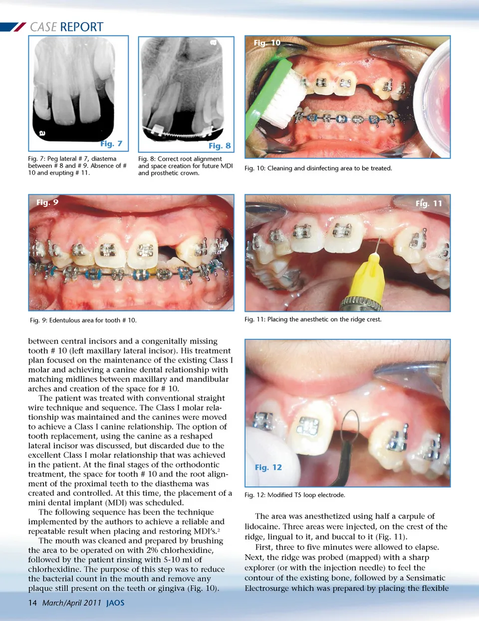
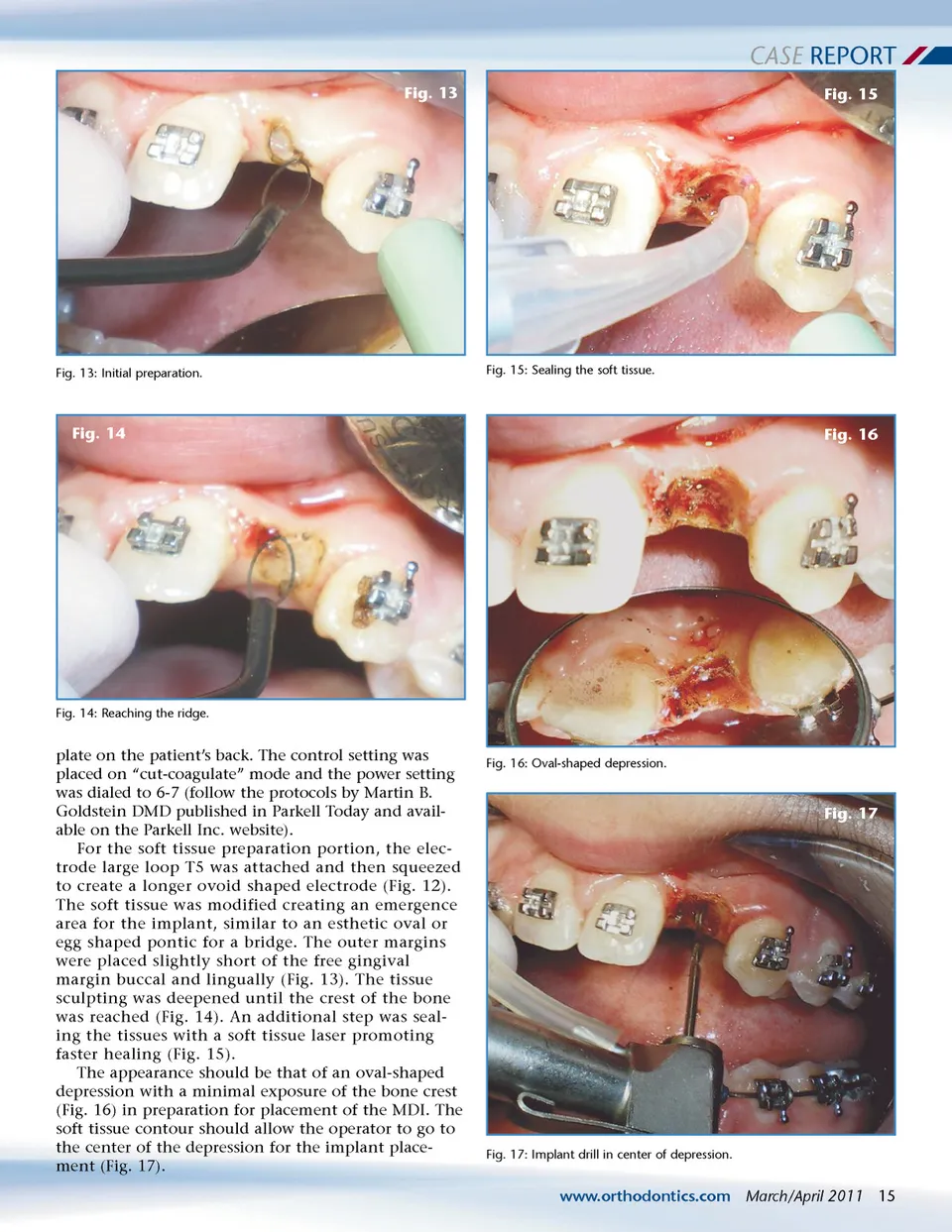
CASE REPORT Fig. 13 Fig. 15 Fig. 13: Initial preparation. Fig. 15: Sealing the soft tissue. Fig. 14 Fig. 16 Fig. 14: Reaching the ridge. plate on the patient’s back. The control setting was placed on “cut-coagulate” mode and the power setting was dialed to 6-7 (follow the protocols by Martin B. Goldstein DMD published in Parkell Today and avail-able on the Parkell Inc. website). For the soft tissue preparation portion, the elec-trode large loop T5 was attached and then squeezed to create a longer ovoid shaped electrode (Fig. 12). The soft tissue was modified creating an emergence area for the implant, similar to an esthetic oval or egg shaped pontic for a bridge. The outer margins were placed slightly short of the free gingival margin buccal and lingually (Fig. 13). The tissue sculpting was deepened until the crest of the bone was reached (Fig. 14). An additional step was seal-ing the tissues with a soft tissue laser promoting faster healing (Fig. 15). The appearance should be that of an oval-shaped depression with a minimal exposure of the bone crest (Fig. 16) in preparation for placement of the MDI. The soft tissue contour should allow the operator to go to the center of the depression for the implant place-ment (Fig. 17). Fig. 16: Oval-shaped depression. Fig. 17 Fig. 17: Implant drill in center of depression. www.orthodontics.com March/April 2011 15
Journal of the American Orthodontic Society March-April 2011: Page 15