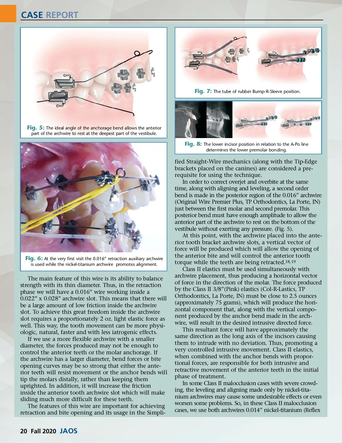
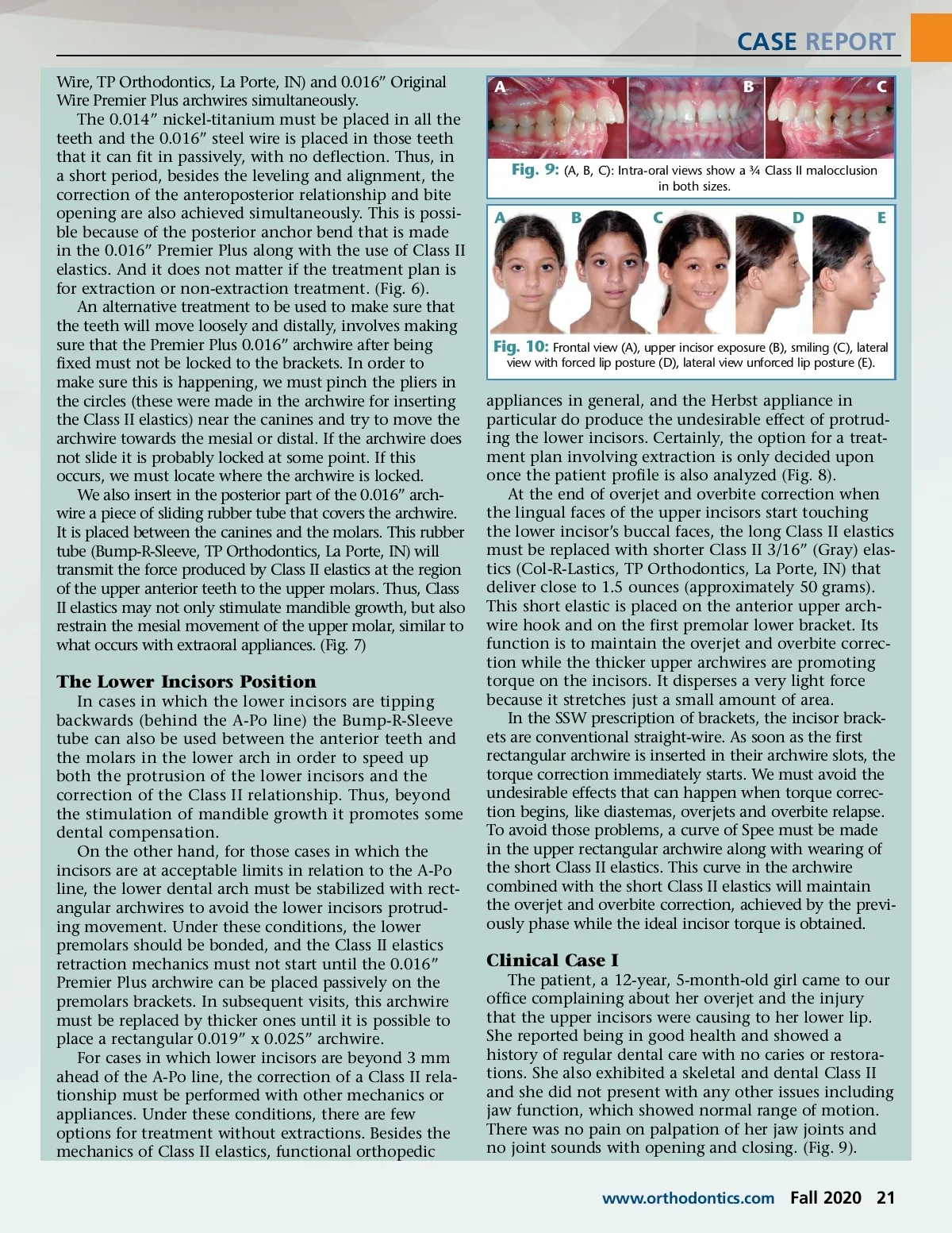
CASE REPORT Fig. 7: The tube of rubber Bump-R-Sleeve position. Fig. 5: The ideal angle of the anchorage bend allows the anterior part of the archwire to rest at the deepest part of the vestibule. Fig. 8: The lower incisor position in relation to the A-Po line determines the lower premolar bonding. Fig. 6: At the very first visit the 0.016” retraction auxiliary archwire is used while the nickel-titanium archwire promotes alignment. The main feature of this wire is its ability to balance strength with its thin diameter. Thus, in the retraction phase we will have a 0.016” wire working inside a 0.022” x 0.028” archwire slot. This means that there will be a large amount of low friction inside the archwire slot. To achieve this great freedom inside the archwire slot requires a proportionately 2 oz. light elastic force as well. This way, the tooth movement can be more physi-ologic, natural, faster and with less iatrogenic effects. If we use a more flexible archwire with a smaller diameter, the forces produced may not be enough to control the anterior teeth or the molar anchorage. If the archwire has a larger diameter, bend forces or bite opening curves may be so strong that either the ante-rior teeth will resist movement or the anchor bends will tip the molars distally, rather than keeping them uprighted. In addition, it will increase the friction inside the anterior tooth archwire slot which will make sliding much more difficult for these teeth. The features of this wire are important for achieving retraction and bite opening and its usage in the Simpli-fied Straight-Wire mechanics (along with the Tip-Edge brackets placed on the canines) are considered a pre-requisite for using the technique. In order to correct overjet and overbite at the same time, along with aligning and leveling, a second order bend is made in the posterior region of the 0.016” archwire (Original Wire Premier Plus, TP Orthodontics, La Porte, IN) just between the first molar and second premolar. This posterior bend must have enough amplitude to allow the anterior part of the archwire to rest on the bottom of the vestibule without exerting any pressure. (Fig. 5). At this point, with the archwire placed into the ante-rior tooth bracket archwire slots, a vertical vector of force will be produced which will allow the opening of the anterior bite and will control the anterior tooth torque while the teeth are being retracted. 18,19 Class II elastics must be used simultaneously with archwire placement, thus producing a horizontal vector of force in the direction of the molar. The force produced by the Class II 3/8”(Pink) elastics (Col-R-Lastics, TP Orthodontics, La Porte, IN) must be close to 2.5 ounces (approximately 75 grams), which will produce the hori-zontal component that, along with the vertical compo-nent produced by the anchor bend made in the arch-wire, will result in the desired intrusive directed force. This resultant force will have approximately the same direction as the long axis of the incisors causing them to intrude with no deviation. Thus, promoting a very controlled intrusive movement. Class II elastics, when combined with the anchor bends with propor-tional forces, are responsible for both intrusive and retractive movement of the anterior teeth in the initial phase of treatment. In some Class II malocclusion cases with severe crowd-ing, the leveling and aligning made only by nickel-tita-nium archwires may cause some undesirable effects or even worsen some problems. So, in these Class II malocclusion cases, we use both archwires 0.014” nickel-titanium (Reflex 20 Fall 2020 JAOS
Journal of the American Orthodontic Society Fall 2020: Page 20