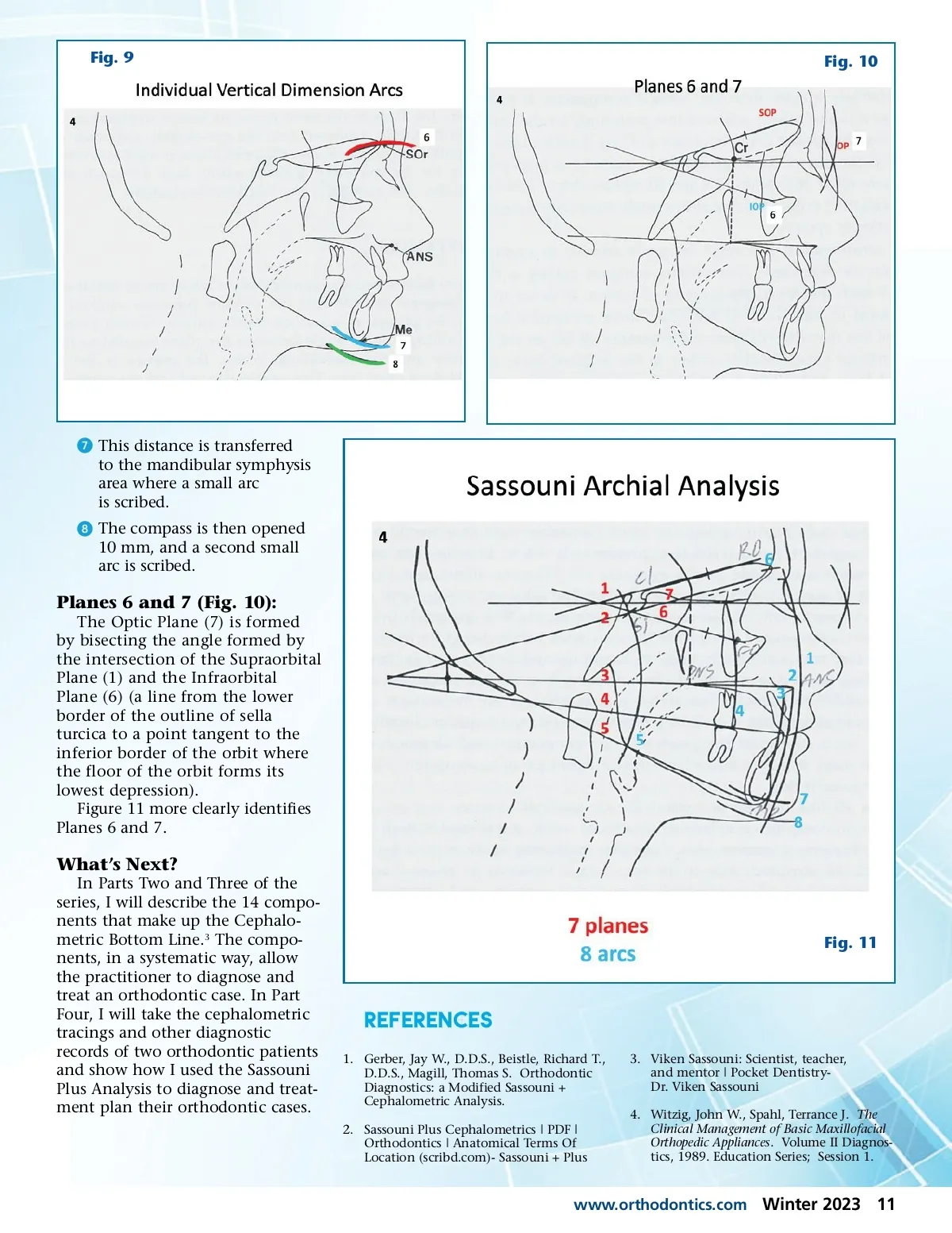
Fig. 9 Fig. 10 ᕧ This distance is transferred to the mandibular symphysis area where a small arc is scribed. ᕨ The compass is then opened 10 mm, and a second small arc is scribed. Planes 6 and 7 (Fig. 10): The Optic Plane (7) is formed by bisecting the angle formed by the intersection of the Supraorbital Plane (1) and the Infraorbital Plane (6) (a line from the lower border of the outline of sella turcica to a point tangent to the inferior border of the orbit where the floor of the orbit forms its lowest depression). Figure 11 more clearly identifies Planes 6 and 7. What’s Next? In Parts Two and Three of the series, I will describe the 14 compo-nents that make up the Cephalo-metric Bottom Line. 3 The compo-nents, in a systematic way, allow the practitioner to diagnose and treat an orthodontic case. In Part Four, I will take the cephalometric tracings and other diagnostic records of two orthodontic patients and show how I used the Sassouni Plus Analysis to diagnose and treat-ment plan their orthodontic cases. Fig. 11 REFERENCES 1. Gerber, Jay W., D.D.S., Beistle, Richard T., D.D.S., Magill, Thomas S. Orthodontic Diagnostics: a Modified Sassouni + Cephalometric Analysis. 2. Sassouni Plus Cephalometrics | PDF | Orthodontics | Anatomical Terms Of Location (scribd.com)-Sassouni + Plus 3. Viken Sassouni: Scientist, teacher, and mentor | Pocket Dentistry-Dr. Viken Sassouni 4. Witzig, John W., Spahl, Terrance J. The Clinical Management of Basic Maxillofacial Orthopedic Appliances . Volume II Diagnos-tics, 1989. Education Series; Session 1. www.orthodontics.com Winter 2023 11
Journal of the American Orthodontic Society Winter 2023: Page 11