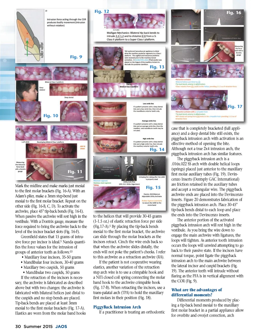
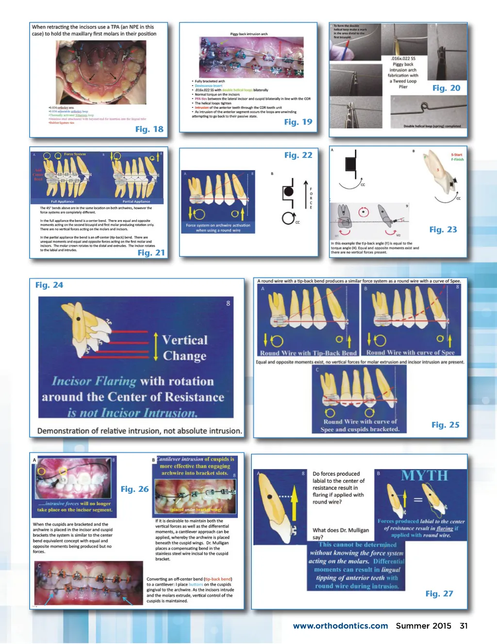
Fig. 12 Fig. 16 Fig. 9 Fig. 13 Fig. 17 Fig. 10 case that is completely bracketed (full appli-ance) and a deep dental bite still exists, the piggyback intrusion arch with activation is an effective method of opening the bite. Although not a true 2x4 intrusion arch, the piggyback intrusion arch has similar features. The piggyback intrusion arch is a .016x.022 SS arch with double helical loops (springs) placed just anterior to the maxillary first molar auxiliary tubes (Fig. 19). Devin-cenzo Inserts (Dentsply GAC International) are friction retained in the auxiliary tubes and accept a rectangular wire. The piggyback archwire ends are placed into the Devincenzo Inserts. Figure 20 demonstrates fabrication of the piggyback intrusion arch. Place 30-45° tip-back bends distal to each loop and place the ends into the Devincenzo inserts. The anterior portion of the activated piggyback intrusion arch will rest high in the vestibule. As you bring the wire down to engage the main archwire with ligatures, the loops will tighten. As anterior tooth intrusion occurs the loops will unwind attempting to go back to their passive state. If the incisors have normal torque, point ligate the piggyback intrusion arch to the main archwire between the lateral incisor and cuspid brackets (Fig. 19). The anterior teeth will intrude without flaring as the PFA is in vertical alignment with the COR (Fig. 9). What are the advantages of differential moments? Differential moments produced by plac-ing a tip-back bend mesial to the maxillary first molar bracket in a partial appliance allow for overbite and overjet correction, arch Fig. 14 Fig. 11 Mark the midline and make marks just mesial to the first molar brackets (Fig. 16-A). With an Adam’s plier, make a 3mm step-bend just mesial to the first molar bracket. Repeat on the other side (Fig. 16-B, C, D). To activate the archwire, place 45° tip-back bends (Fig. 16-E). When passive the archwire will rest high in the vestibule. With a Dontrix gauge, measure the force required to bring the archwire back to the level of the incisor bracket slots (Fig. 16-F). Greenfield states that 15 grams of intru-sive force per incisor is ideal. 5 Nanda quanti-fies the force values for the intrusion of groups of anterior teeth as follows: 10 • Maxillary four incisors, 35-50 grams • Mandibular four incisors, 30-40 grams • Maxillary two cuspids, 50 grams • Mandibular two cuspids, 50 grams If the retraction of the incisors is neces-sary, the archwire is fabricated as described above but with two changes: the archwire is fabricated with bilateral helices just distal to the cuspids and no step bends are placed. Tip-back bends are placed at least 3mm mesial to the first molar brackets (Fig. 17-A). Elastics are worn from the molar band hooks 30 Summer 2015 JAOS Fig. 15 to the helices that will provide 30-45 grams (1-1.5 oz.) of elastic retraction force per side (Fig.17-A). 5 By placing the tip-back bends mesial to the first molar bracket, the archwire can slide through the molar brackets as the incisors retract. Cinch the wire ends back so that when the archwire slides distally, the ends will not poke the patient’s cheeks. I refer to this archwire as a retraction archwire (RA). If the patient is not cooperative wearing elastics, another variation of the retraction step arch wire is to use a crimpable hook and a NiTi closed coil spring connecting the molar band hook to the archwire crimpable hook (Fig. 17-B). When retracting the incisors, use a trans-palatal arch (TPA) to hold the maxillary first molars in their position (Fig. 18). PiggyBack Intrusion Arch If a practitioner is treating an orthodontic
Journal of the American Orthodontic Society Summer 2015-Buyer's Guide: Page 30