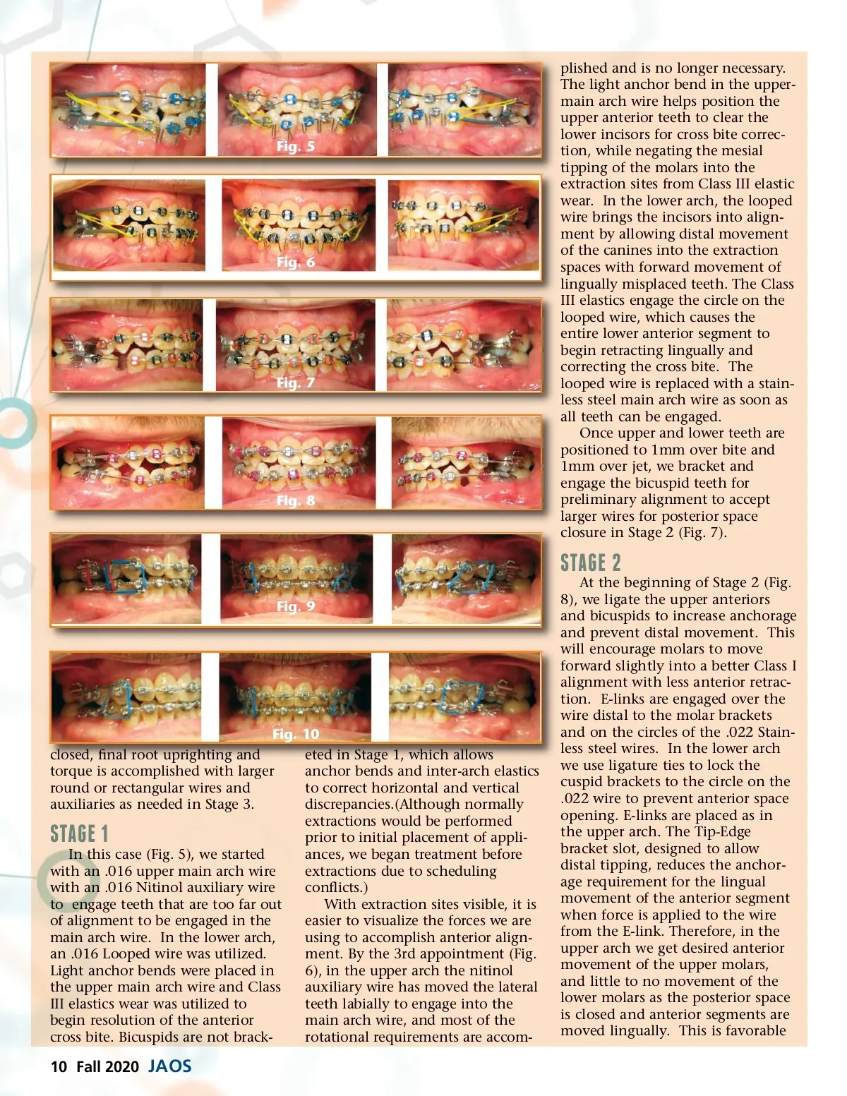
Fig. 5 Fig. 6 Fig. 7 Fig. 8 plished and is no longer necessary. The light anchor bend in the upper-main arch wire helps position the upper anterior teeth to clear the lower incisors for cross bite correc-tion, while negating the mesial tipping of the molars into the extraction sites from Class III elastic wear. In the lower arch, the looped wire brings the incisors into align-ment by allowing distal movement of the canines into the extraction spaces with forward movement of lingually misplaced teeth. The Class III elastics engage the circle on the looped wire, which causes the entire lower anterior segment to begin retracting lingually and correcting the cross bite. The looped wire is replaced with a stain-less steel main arch wire as soon as all teeth can be engaged. Once upper and lower teeth are positioned to 1mm over bite and 1mm over jet, we bracket and engage the bicuspid teeth for preliminary alignment to accept larger wires for posterior space closure in Stage 2 (Fig. 7). STAGE 2 Fig. 9 At the beginning of Stage 2 (Fig. 8), we ligate the upper anteriors and bicuspids to increase anchorage and prevent distal movement. This will encourage molars to move forward slightly into a better Class I alignment with less anterior retrac-tion. E-links are engaged over the wire distal to the molar brackets and on the circles of the .022 Stain-less steel wires. In the lower arch we use ligature ties to lock the cuspid brackets to the circle on the .022 wire to prevent anterior space opening. E-links are placed as in the upper arch. The Tip-Edge bracket slot, designed to allow distal tipping, reduces the anchor-age requirement for the lingual movement of the anterior segment when force is applied to the wire from the E-link. Therefore, in the upper arch we get desired anterior movement of the upper molars, and little to no movement of the lower molars as the posterior space is closed and anterior segments are moved lingually. This is favorable Fig. 10 closed, final root uprighting and eted in Stage 1, which allows torque is accomplished with larger anchor bends and inter-arch elastics round or rectangular wires and to correct horizontal and vertical auxiliaries as needed in Stage 3. discrepancies.(Although normally extractions would be performed prior to initial placement of appli-In this case (Fig. 5), we started ances, we began treatment before with an .016 upper main arch wire extractions due to scheduling with an .016 Nitinol auxiliary wire conflicts.) to engage teeth that are too far out With extraction sites visible, it is of alignment to be engaged in the easier to visualize the forces we are main arch wire. In the lower arch, using to accomplish anterior align-an .016 Looped wire was utilized. ment. By the 3rd appointment (Fig. Light anchor bends were placed in 6), in the upper arch the nitinol the upper main arch wire and Class auxiliary wire has moved the lateral III elastics wear was utilized to teeth labially to engage into the begin resolution of the anterior main arch wire, and most of the cross bite. Bicuspids are not brack-rotational requirements are accom-STAGE 1 10 Fall 2020 JAOS
Journal of the American Orthodontic Society Fall 2020: Page 10