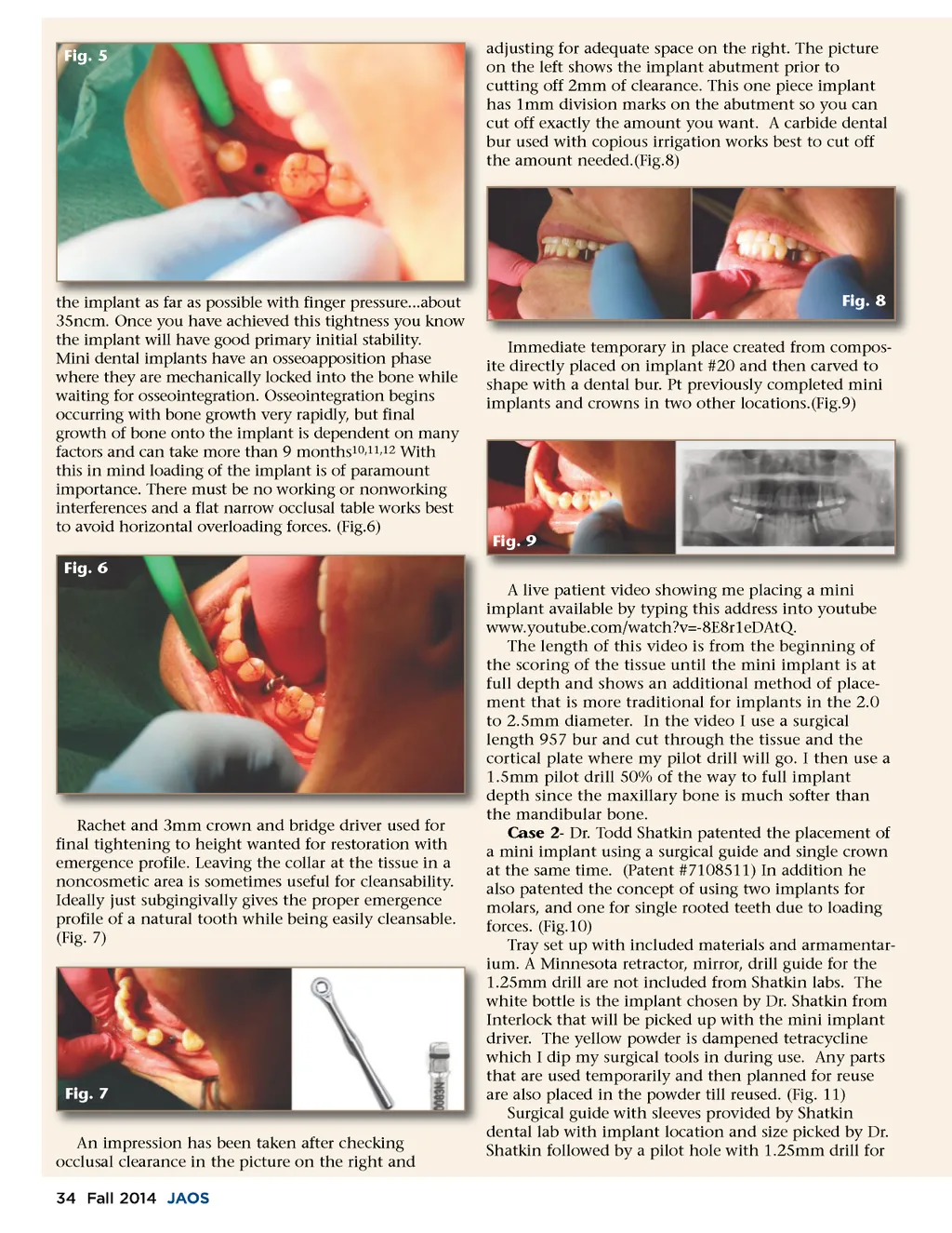
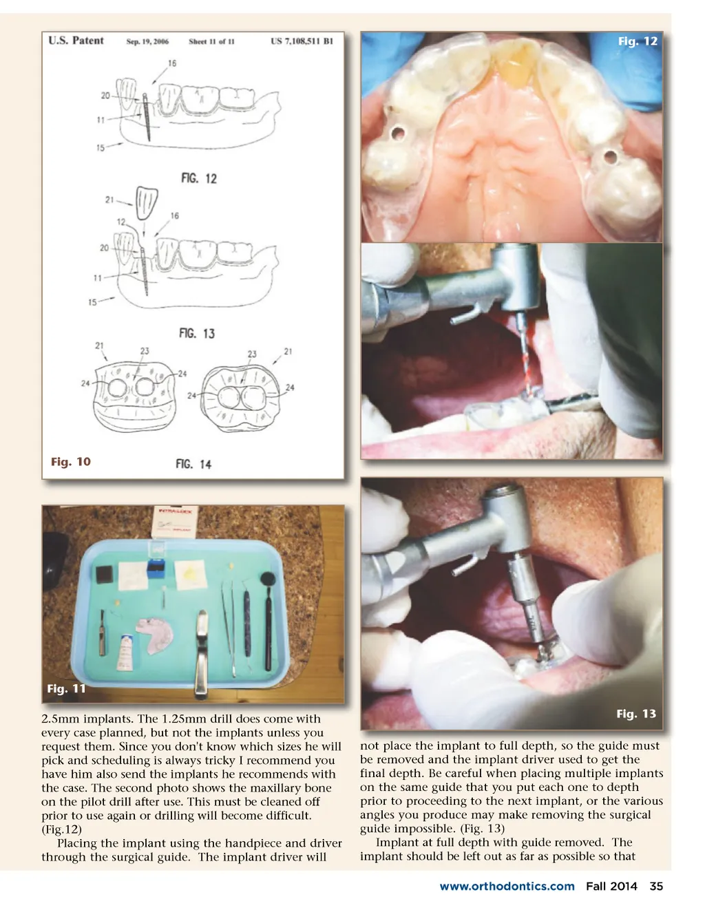
Fig. 5 adjusting for adequate space on the right. The picture on the left shows the implant abutment prior to cutting off 2mm of clearance. This one piece implant has 1mm division marks on the abutment so you can cut off exactly the amount you want. A carbide dental bur used with copious irrigation works best to cut off the amount needed.(Fig.8) finger pressure...about the implant as far as possible with fi f nger pressure about 35ncm. Once you have achieved this tightness you know the implant will have good primary initial stability. Mini dental implants have an osseoapposition phase where they are mechanically locked into the bone while waiting for osseointegration. Osseointegration begins occurring with bone growth very rapidly, but final growth of bone onto the implant is dependent on many factors and can take more than 9 months 10,11,12 With this in mind loading of the implant is of paramount importance. There must be no working or nonworking interferences and a flat narrow occlusal table works best to avoid horizontal overloading forces. (Fig.6) Fig. 6 Fig. 8 Immediate temporary in place created from compos-ite directly placed on implant #20 and then carved to shape with a dental bur. Pt previously completed mini implants and crowns in two other locations.(Fig.9) Fig. 9 A live patient video showing me placing a mini implant available by typing this address into youtube www.youtube.com/watch?v=-8E8r1eDAtQ. The length of this video is from the beginning of the scoring of the tissue until the mini implant is at full depth and shows an additional method of place-ment that is more traditional for implants in the 2.0 to 2.5mm diameter. In the video I use a surgical length 957 bur and cut through the tissue and the cortical plate where my pilot drill will go. I then use a 1.5mm pilot drill 50% of the way to full implant depth since the maxillary bone is much softer than the mandibular bone. Case 2 -Dr. Todd Shatkin patented the placement of a mini implant using a surgical guide and single crown at the same time. (Patent #7108511) In addition he also patented the concept of using two implants for molars, and one for single rooted teeth due to loading forces. (Fig.10) Tray set up with included materials and armamentar-ium. A Minnesota retractor, mirror, drill guide for the 1.25mm drill are not included from Shatkin labs. The white bottle is the implant chosen by Dr. Shatkin from Interlock that will be picked up with the mini implant driver. The yellow powder is dampened tetracycline which I dip my surgical tools in during use. Any parts that are used temporarily and then planned for reuse are also placed in the powder till reused. (Fig. 11) Surgical guide with sleeves provided by Shatkin dental lab with implant location and size picked by Dr. Shatkin followed by a pilot hole with 1.25mm drill for Rachet and 3mm crown and bridge driver used for final tightening to height wanted for restoration with emergence profile. Leaving the collar at the tissue in a noncosmetic area is sometimes useful for cleansability. Ideally just subgingivally gives the proper emergence profile of a natural tooth while being easily cleansable. (Fig. 7) Fig. 7 An impression has been taken after checking occlusal clearance in the picture on the right and 34 Fall 2014 JAOS
Journal of the American Orthodontic Society Fall 2014: Page 34