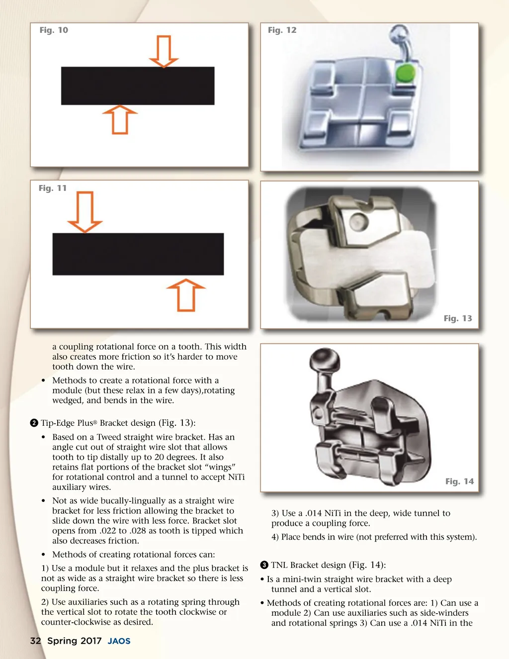
Fig. 10 Fig. 12 Fig. 11 Fig. 13 a coupling rotational force on a tooth. This width also creates more friction so it’s harder to move tooth down the wire. • Methods to create a rotational force with a module (but these relax in a few days),rotating wedged, and bends in the wire. ᕢ Tip-Edge Plus ® Bracket design (Fig. 13) : • Based on a Tweed straight wire bracket. Has an angle cut out of straight wire slot that allows tooth to tip distally up to 20 degrees. It also retains flat portions of the bracket slot “wings” for rotational control and a tunnel to accept NiTi auxiliary wires. • Not as wide bucally-lingually as a straight wire bracket for less friction allowing the bracket to slide down the wire with less force. Bracket slot opens from .022 to .028 as tooth is tipped which also decreases friction. • Methods of creating rotational forces can: 1) Use a module but it relaxes and the plus bracket is not as wide as a straight wire bracket so there is less coupling force. 2) Use auxiliaries such as a rotating spring through the vertical slot to rotate the tooth clockwise or counter-clockwise as desired. Fig. 14 3) Use a .014 NiTi in the deep, wide tunnel to produce a coupling force. 4) Place bends in wire (not preferred with this system). ᕣ TNL Bracket design (Fig. 14) : • Is a mini-twin straight wire bracket with a deep tunnel and a vertical slot. • Methods of creating rotational forces are: 1) Can use a module 2) Can use auxiliaries such as side-winders and rotational springs 3) Can use a .014 NiTi in the 32 Spring 2017 JAOS
Journal of the American Orthodontic Society Spring 2017: Page 32